QoS
This section describes how to use QoS functions that can be set using REST.
About QoS
QoS (Quality of Service) is a technology that can transfer the data in accordance with the priority based on the type of data, and reserve network bandwidth for a particular communication in order to communicate with a constant communication bandwidth on the network.
Example of the operation of the per-flow QoS
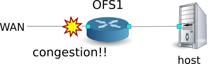
The following shows an example of creating topology, adding Queue settings and rules to reserve network bandwidth. And this example shows traffic shaping at WAN side interface of OFS1.
Building the environment
First, build an environment on Mininet. Parameters of the mn command are as
follows.
| Parameters | Value | Explanation |
|---|---|---|
| mac | None | Set the MAC address of the host automatically |
| switch | ovsk | Use Open vSwitch |
| controller | remote | Use an external one for OpenFlow controller |
| x | None | Start xterm |
An execution example is as follows.
$ sudo mn --mac --switch ovsk --controller remote -x
*** Creating network
*** Adding controller
Unable to contact the remote controller at 127.0.0.1:6633
*** Adding hosts:
h1 h2
*** Adding switches:
s1
*** Adding links:
(h1, s1) (h2, s1)
*** Configuring hosts
h1 h2
*** Running terms on localhost:10.0
*** Starting controller
*** Starting 1 switches
s1
*** Starting CLI:
mininet>
Also, start another xterm for the controller.
mininet> xterm c0
mininet>
Next, set the version of OpenFlow to be used in each router to version 1.3 and set to listen on port 6632 to access OVSDB.
switch: s1 (root):
# ovs-vsctl set Bridge s1 protocols=OpenFlow13
# ovs-vsctl set-manager ptcp:6632
Then, modify simple_switch_13.py used in “Switching Hub”. rest_qos.py suppose to be processed on Flow Table pipeline processing, modify simple_switch_13.py to register flow entry into table id:1.
controller: c0 (root)
# sed '/OFPFlowMod(/,/)/s/)/, table_id=1)/' ryu/ryu/app/simple_switch_13.py > ryu/ryu/app/qos_simple_switch_13.py
# cd ryu/; python ./setup.py install
Finally, start rest_qos, qos_simple_switch_13 and rest_conf_switch on xterm of controller.
controller: c0 (root):
# ryu-manager ryu.app.rest_qos ryu.app.qos_simple_switch_13 ryu.app.rest_conf_switch
loading app ryu.app.rest_qos
loading app ryu.app.qos_simple_switch_13
loading app ryu.app.rest_conf_switch
loading app ryu.controller.ofp_handler
loading app ryu.controller.ofp_handler
loading app ryu.controller.ofp_handler
instantiating app None of DPSet
creating context dpset
instantiating app None of ConfSwitchSet
creating context conf_switch
creating context wsgi
instantiating app ryu.app.rest_conf_switch of ConfSwitchAPI
instantiating app ryu.app.qos_simple_switch_13 of SimpleSwitch13
instantiating app ryu.controller.ofp_handler of OFPHandler
instantiating app ryu.app.rest_qos of RestQoSAPI
(3519) wsgi starting up on http://0.0.0.0:8080/
After a successful connection between the router and Ryu, the following message appears.
controller: c0 (root):
[QoS][INFO] dpid=0000000000000001: Join qos switch.
If the above log is displayed for the three routers, preparation is complete.
Queue Setting
Set the Queue to switch.
| Queue ID | Max rate | Min rate |
|---|---|---|
| 0 | 500Kbps | - |
| 1 | (1Mbps) | 800Kbps |
Note
For details of REST API used in the following description, see “REST API List” at the end of the section.
First, set ovsdb_addr in order to access OVSDB.
Node: c0 (root):
# curl -X PUT -d '"tcp:127.0.0.1:6632"' http://localhost:8080/v1.0/conf/switches/0000000000000001/ovsdb_addr
#
Also, execute setting of Queue.
# curl -X POST -d '{"port_name": "s1-eth1", "type": "linux-htb", "max_rate": "1000000", "queues": [{"max_rate": "500000"}, {"min_rate": "800000"}]}' http://localhost:8080/qos/queue/0000000000000001
  [
    {
      "switch_id": "0000000000000001",
      "command_result": {
        "result": "success",
        "details": {
          "0": {
            "config": {
              "max-rate": "500000"
            }
          },
          "1": {
            "config": {
              "min-rate": "800000"
            }
          }
        }
      }
    }
  ]
Note
The result of the REST command is formatted for easy viewing.
QoS Setting
Install the following flow entry to the switch.
| (Priority) | Destination address | Destination port | Protocol | Queue ID | (QoS ID) |
|---|---|---|---|---|---|
| 1 | 10.0.0.1 | 5002 | UDP | 1 | 1 |
Node: c0 (root):
# curl -X POST -d '{"match": {"nw_dst": "10.0.0.1", "nw_proto": "UDP", "tp_dst": "5002"}, "actions":{"queue": "1"}}' http://localhost:8080/qos/rules/0000000000000001
  [
    {
      "switch_id": "0000000000000001",
      "command_result": [
        {
          "result": "success",
          "details": "QoS added. : qos_id=1"
        }
      ]
    }
  ]
Verifying the Setting
Check the contents of the setting of the switch.
Node: c0 (root):
# curl -X GET http://localhost:8080/qos/rules/0000000000000001
  [
    {
      "switch_id": "0000000000000001",
      "command_result": [
        {
          "qos": [
            {
              "priority": 1,
              "dl_type": "IPv4",
              "nw_proto": "UDP",
              "tp_dst": 5002,
              "qos_id": 1,
              "nw_dst": "10.0.0.1",
              "actions": [
                {
                  "queue": "1"
                }
              ]
            }
          ]
        }
      ]
    }
  ]
Measuring the bandwidth
Try to measure the bandwidth by using iperf. In the following example, h1(server) listens on the port 5001 and 5002 with UDP protocol. h2(client) sends 1Mbps UDP traffic to the port 5001 on h1 and 1Mbps UDP traffic to the port 5002 on h1
Note
The fallowing examples use iperf (http://iperf.fr/) to measure the bandwidth. But this document does not describe how to install iperf and how to use it.
First, start another xterm on each h1 and h2.
mininet> xterm h1
mininet> xterm h2
Node: h1(1) (root):
# iperf -s -u -i 1 -p 5001
...
Node: h1(2) (root):
# iperf -s -u -i 1 -p 5002
...
Node: h2(1) (root):
# iperf -c 10.0.0.1 -p 5001 -u -b 1M
...
Node: h2(2) (root):
# iperf -c 10.0.0.1 -p 5002 -u -b 1M
...
Node: h1(1) (root):
[  4] local 10.0.0.1 port 5001 connected with 10.0.0.2 port 50375
[ ID] Interval       Transfer     Bandwidth        Jitter   Lost/Total Datagrams
[  4]  0.0- 1.0 sec  60.3 KBytes   494 Kbits/sec  12.208 ms    4/   42 (9.5%)
[  4]  0.0- 1.0 sec  4 datagrams received out-of-order
[  4]  1.0- 2.0 sec  58.9 KBytes   482 Kbits/sec  12.538 ms    0/   41 (0%)
[  4]  2.0- 3.0 sec  58.9 KBytes   482 Kbits/sec  12.494 ms    0/   41 (0%)
[  4]  3.0- 4.0 sec  58.9 KBytes   482 Kbits/sec  12.625 ms    0/   41 (0%)
[  4]  4.0- 5.0 sec  58.9 KBytes   482 Kbits/sec  12.576 ms    0/   41 (0%)
[  4]  5.0- 6.0 sec  58.9 KBytes   482 Kbits/sec  12.561 ms    0/   41 (0%)
[  4]  6.0- 7.0 sec  11.5 KBytes  94.1 Kbits/sec  45.536 ms    0/    8 (0%)
[  4]  7.0- 8.0 sec  4.31 KBytes  35.3 Kbits/sec  92.790 ms    0/    3 (0%)
[  4]  8.0- 9.0 sec  4.31 KBytes  35.3 Kbits/sec  135.391 ms    0/    3 (0%)
[  4]  9.0-10.0 sec  4.31 KBytes  35.3 Kbits/sec  167.045 ms    0/    3 (0%)
[  4] 10.0-11.0 sec  4.31 KBytes  35.3 Kbits/sec  193.006 ms    0/    3 (0%)
[  4] 11.0-12.0 sec  4.31 KBytes  35.3 Kbits/sec  213.944 ms    0/    3 (0%)
[  4] 12.0-13.0 sec  4.31 KBytes  35.3 Kbits/sec  231.981 ms    0/    3 (0%)
[  4] 13.0-14.0 sec  4.31 KBytes  35.3 Kbits/sec  249.758 ms    0/    3 (0%)
[  4] 14.0-15.0 sec  4.31 KBytes  35.3 Kbits/sec  261.139 ms    0/    3 (0%)
[  4] 15.0-16.0 sec  4.31 KBytes  35.3 Kbits/sec  269.879 ms    0/    3 (0%)
[  4] 16.0-17.0 sec  12.9 KBytes   106 Kbits/sec  204.755 ms    0/    9 (0%)
[  4] 17.0-18.0 sec  58.9 KBytes   482 Kbits/sec  26.214 ms    0/   41 (0%)
[  4] 18.0-19.0 sec  58.9 KBytes   482 Kbits/sec  13.485 ms    0/   41 (0%)
[  4] 19.0-20.0 sec  58.9 KBytes   482 Kbits/sec  12.690 ms    0/   41 (0%)
[  4] 20.0-21.0 sec  58.9 KBytes   482 Kbits/sec  12.498 ms    0/   41 (0%)
[  4] 21.0-22.0 sec  58.9 KBytes   482 Kbits/sec  12.601 ms    0/   41 (0%)
[  4] 22.0-23.0 sec  60.3 KBytes   494 Kbits/sec  12.640 ms    0/   42 (0%)
[  4] 23.0-24.0 sec  58.9 KBytes   482 Kbits/sec  12.508 ms    0/   41 (0%)
[  4] 24.0-25.0 sec  58.9 KBytes   482 Kbits/sec  12.578 ms    0/   41 (0%)
[  4] 25.0-26.0 sec  58.9 KBytes   482 Kbits/sec  12.541 ms    0/   41 (0%)
[  4] 26.0-27.0 sec  58.9 KBytes   482 Kbits/sec  12.539 ms    0/   41 (0%)
[  4] 27.0-28.0 sec  58.9 KBytes   482 Kbits/sec  12.578 ms    0/   41 (0%)
[  4] 28.0-29.0 sec  58.9 KBytes   482 Kbits/sec  12.527 ms    0/   41 (0%)
[  4] 29.0-30.0 sec  58.9 KBytes   482 Kbits/sec  12.542 ms    0/   41 (0%)
[  4]  0.0-30.6 sec  1.19 MBytes   327 Kbits/sec  12.562 ms    4/  852 (0.47%)
[  4]  0.0-30.6 sec  4 datagrams received out-of-order
Node: h1(2) (root):
[  4] local 10.0.0.1 port 5002 connected with 10.0.0.2 port 60868
[ ID] Interval       Transfer     Bandwidth        Jitter   Lost/Total Datagrams
[  4]  0.0- 1.0 sec   112 KBytes   917 Kbits/sec   4.288 ms    0/   78 (0%)
[  4]  1.0- 2.0 sec   115 KBytes   941 Kbits/sec   4.168 ms    0/   80 (0%)
[  4]  2.0- 3.0 sec   115 KBytes   941 Kbits/sec   4.454 ms    0/   80 (0%)
[  4]  3.0- 4.0 sec   113 KBytes   929 Kbits/sec   4.226 ms    0/   79 (0%)
[  4]  4.0- 5.0 sec   113 KBytes   929 Kbits/sec   4.096 ms    0/   79 (0%)
[  4]  5.0- 6.0 sec   113 KBytes   929 Kbits/sec   4.225 ms    0/   79 (0%)
[  4]  6.0- 7.0 sec   113 KBytes   929 Kbits/sec   4.055 ms    0/   79 (0%)
[  4]  7.0- 8.0 sec   113 KBytes   929 Kbits/sec   4.241 ms    0/   79 (0%)
[  4]  8.0- 9.0 sec   115 KBytes   941 Kbits/sec   3.886 ms    0/   80 (0%)
[  4]  9.0-10.0 sec   112 KBytes   917 Kbits/sec   3.969 ms    0/   78 (0%)
[  4]  0.0-10.8 sec  1.19 MBytes   931 Kbits/sec   4.287 ms    0/  852 (0%)
The above result shows the traffic sent to the port 5001 is shaped with up to 500Kbps and the traffic to the port 5002 is guaranteed 800Kbps bandwidth.
Example of the operation of QoS by using DiffServ
Previous example shows the per-flow QoS, while it is able to control finely, as the communication flows increase, the flow entries which are set for each switch to control the bandwidth also increase. So the per-flow QoS is not scalable. Therefore, the following example divides flows into the several QoS classes at the entrance router of DiffServ domain and applies DiffServ to control flows for each class. DiffServ forward the packets according to PHB defined by DSCP value which is the first 6-bit of ToS field in IP header, and realizes QoS.
The following shows an example of setting Queue and bandwidth configuration based on the QoS class into Switch (Router) OFS1, and installation rules of marking the DSCP value in accordance with the flow. And this example shows traffic shaping at WAN side interface of OFS1.

Building the environment
First, build an environment on Mininet. Parameters of the mn command are as
follows.
| Parameters | Value | Explanation |
|---|---|---|
| topo | linear,2 | Topology where two switches are connected serially |
| mac | None | Set the MAC address of the host automatically |
| switch | ovsk | Use Open vSwitch |
| controller | remote | Use an external one for OpenFlow controller |
| x | None | Start xterm |
An execution example is as follows.
$ sudo mn --topo linear,2 --mac --switch ovsk --controller remote -x
*** Creating network
*** Adding controller
Unable to contact the remote controller at 127.0.0.1:6633
*** Adding hosts:
h1 h2
*** Adding switches:
s1
*** Adding links:
(h1, s1) (h2, s1)
*** Configuring hosts
h1 h2
*** Running terms on localhost:10.0
*** Starting controller
*** Starting 1 switches
s1
*** Starting CLI:
mininet>
Also, start another xterm for the controller.
mininet> xterm c0
mininet>
Next, set the version of OpenFlow to be used in each router to version 1.3 and set to listen on port 6632 to access OVSDB.
switch: s1 (root):
# ovs-vsctl set Bridge s1 protocols=OpenFlow13
# ovs-vsctl set-manager ptcp:6632
switch: s2 (root):
# ovs-vsctl set Bridge s2 protocols=OpenFlow13
Then, delete the IP address that is assigned automatically on each host and set a new IP address.
host: h1:
# ip addr del 10.0.0.1/8 dev h1-eth0
# ip addr add 172.16.20.10/24 dev h1-eth0
host: h2:
# ip addr del 10.0.0.2/8 dev h2-eth0
# ip addr add 172.16.10.10/24 dev h2-eth0
And, modify rest_router.py used in “Router”. rest_qos.py suppose to be processed on Flow Table pipeline processing, modify rest_router.py to register flow entry into table id:1.
controller: c0 (root):
# sed '/OFPFlowMod(/,/)/s/0, cmd/1, cmd/' ryu/ryu/app/rest_router.py > ryu/ryu/app/qos_rest_router.py
# cd ryu/; python ./setup.py install
Finally, start rest_qos, qos_rest_router and rest_conf_switch on xterm of controller.
controller: c0 (root):
# ryu-manager ryu.app.rest_qos ryu.app.qos_rest_router ryu.app.rest_conf_switch
loading app ryu.app.rest_qos
loading app ryu.app.qos_rest_router
loading app ryu.app.rest_conf_switch
loading app ryu.controller.ofp_handler
loading app ryu.controller.ofp_handler
loading app ryu.controller.ofp_handler
loading app ryu.controller.ofp_handler
instantiating app None of DPSet
creating context dpset
instantiating app None of ConfSwitchSet
creating context conf_switch
creating context wsgi
instantiating app ryu.app.rest_conf_switch of ConfSwitchAPI
instantiating app ryu.app.qos_rest_router of RestRouterAPI
instantiating app ryu.controller.ofp_handler of OFPHandler
instantiating app ryu.app.rest_qos of RestQoSAPI
(4687) wsgi starting up on http://0.0.0.0:8080/
After a successful connection between the router and Ryu, the following message appears.
controller: c0 (root):
[RT][INFO] switch_id=0000000000000002: Set SW config for TTL error packet in.
[RT][INFO] switch_id=0000000000000002: Set ARP handling (packet in) flow [cookie=0x0]
[RT][INFO] switch_id=0000000000000002: Set L2 switching (normal) flow [cookie=0x0]
[RT][INFO] switch_id=0000000000000002: Set default route (drop) flow [cookie=0x0]
[RT][INFO] switch_id=0000000000000002: Start cyclic routing table update.
[RT][INFO] switch_id=0000000000000002: Join as router.
[QoS][INFO] dpid=0000000000000002: Join qos switch.
[RT][INFO] switch_id=0000000000000001: Set SW config for TTL error packet in.
[RT][INFO] switch_id=0000000000000001: Set ARP handling (packet in) flow [cookie=0x0]
[RT][INFO] switch_id=0000000000000001: Set L2 switching (normal) flow [cookie=0x0]
[RT][INFO] switch_id=0000000000000001: Set default route (drop) flow [cookie=0x0]
[RT][INFO] switch_id=0000000000000001: Start cyclic routing table update.
[RT][INFO] switch_id=0000000000000001: Join as router.
[QoS][INFO] dpid=0000000000000001: Join qos switch.
If the above log is displayed for the three routers, preparation is complete.
Queue Setting
| Queue ID | Max rate | Min rate | Class |
|---|---|---|---|
| 0 | 1Mbps | - | Default |
| 1 | (1Mbps) | 200Kbps | AF3 |
| 2 | (1Mbps) | 500Kbps | AF4 |
Note
For details of REST API used in the following description, see “REST API List” at the end of the section.
First, set ovsdb_addr in order to access OVSDB.
Node: c0 (root):
# curl -X PUT -d '"tcp:127.0.0.1:6632"' http://localhost:8080/v1.0/conf/switches/0000000000000001/ovsdb_addr
#
Also, execute setting of Queue.
# curl -X POST -d '{"port_name": "s1-eth1", "type": "linux-htb", "max_rate": "1000000", "queues":[{"max_rate": "1000000"}, {"min_rate": "200000"}, {"min_rate": "500000"}]}' http://localhost:8080/qos/queue/0000000000000001
  [
    {
      "switch_id": "0000000000000001",
      "command_result": {
        "result": "success",
        "details": {
          "0": {
            "config": {
              "max-rate": "1000000"
            }
          },
          "1": {
            "config": {
              "min-rate": "200000"
            }
          },
          "2": {
            "config": {
              "min-rate": "500000"
            }
          }
        }
      }
    }
  ]
Note
The result of the REST command is formatted for easy viewing.
Router Setting
Set the IP address and the default route for each router.
# curl -X POST -d '{"address": "172.16.20.1/24"}' http://localhost:8080/router/0000000000000001
  [
    {
      "switch_id": "0000000000000001",
      "command_result": [
        {
          "result": "success",
          "details": "Add address [address_id=1]"
        }
      ]
    }
  ]

# curl -X POST -d '{"address": "172.16.30.10/24"}' http://localhost:8080/router/0000000000000001
  [
    {
      "switch_id": "0000000000000001",
      "command_result": [
        {
          "result": "success",
          "details": "Add address [address_id=2]"
        }
      ]
    }
  ]

# curl -X POST -d '{"gateway": "172.16.30.1"}' http://localhost:8080/router/0000000000000001
  [
    {
      "switch_id": "0000000000000001",
      "command_result": [
        {
          "result": "success",
          "details": "Add route [route_id=1]"
        }
      ]
    }
  ]

# curl -X POST -d '{"address": "172.16.10.1/24"}' http://localhost:8080/router/0000000000000002
  [
    {
      "switch_id": "0000000000000002",
      "command_result": [
        {
          "result": "success",
          "details": "Add address [address_id=1]"
        }
      ]
    }
  ]

# curl -X POST -d '{"address": "172.16.30.1/24"}' http://localhost:8080/router/0000000000000002
  [
    {
      "switch_id": "0000000000000002",
      "command_result": [
        {
          "result": "success",
          "details": "Add address [address_id=2]"
        }
      ]
    }
  ]

# curl -X POST -d '{"gateway": "172.16.30.10"}' http://localhost:8080/router/0000000000000002
  [
    {
      "switch_id": "0000000000000002",
      "command_result": [
        {
          "result": "success",
          "details": "Add route [route_id=1]"
        }
      ]
    }
  ]
...
The IP address settings for each router are done, register the routers as the default gateway to each host.
host: h1:
# ip route add default via 172.16.20.1
host: h2:
# ip route add default via 172.16.10.1
QoS Setting
Install the following flow entry in accordance with DSCP value into the router (s1).
| Priority | DSCP | Queue ID | (QoS ID) |
|---|---|---|---|
| 1 | 26(AF31) | 1 | 1 |
| 1 | 34(AF41) | 2 | 2 |
Node: c0 (root):
# curl -X POST -d '{"match": {"ip_dscp": "26"}, "actions":{"queue": "1"}}' http://localhost:8080/qos/rules/0000000000000001
  [
    {
      "switch_id": "0000000000000001",
      "command_result": [
        {
          "result": "success",
          "details": "QoS added. : qos_id=1"
        }
      ]
    }
  ]

# curl -X POST -d '{"match": {"ip_dscp": "34"}, "actions":{"queue": "2"}}' http://localhost:8080/qos/rules/0000000000000001
  [
    {
      "switch_id": "0000000000000001",
      "command_result": [
        {
          "result": "success",
          "details": "QoS added. : qos_id=2"
        }
      ]
    }
  ]
Install the following rules of marking the DSCP value into the router (s2).
| (Priority) | Destination address | Destination port | Protocol | DSCP | (QoS ID) |
|---|---|---|---|---|---|
| 1 | 172.16.20.10 | 5002 | UDP | 26(AF31) | 1 |
| 1 | 172.16.20.10 | 5003 | UDP | 34(AF41) | 2 |
Node: c0 (root):
# curl -X POST -d '{"match": {"nw_dst": "172.16.20.10", "nw_proto": "UDP", "tp_dst": "5002"}, "actions":{"mark": "26"}}' http://localhost:8080/qos/rules/0000000000000002
  [
    {
      "switch_id": "0000000000000002",
      "command_result": [
        {
          "result": "success",
          "details": "QoS added. : qos_id=1"
        }
      ]
    }
  ]

# curl -X POST -d '{"match": {"nw_dst": "172.16.20.10", "nw_proto": "UDP", "tp_dst": "5003"}, "actions":{"mark": "34"}}' http://localhost:8080/qos/rules/0000000000000002
  [
    {
      "switch_id": "0000000000000002",
      "command_result": [
        {
          "result": "success",
          "details": "QoS added. : qos_id=2"
        }
      ]
    }
  ]
Verifying the Setting
Check the contents of the setting of each switch.
Node: c0 (root):
# curl -X GET http://localhost:8080/qos/rules/0000000000000001
  [
    {
      "switch_id": "0000000000000001",
      "command_result": [
        {
          "qos": [
            {
              "priority": 1,
              "dl_type": "IPv4",
              "ip_dscp": 34,
              "actions": [
                {
                  "queue": "2"
                }
              ],
              "qos_id": 2
            },
            {
              "priority": 1,
              "dl_type": "IPv4",
              "ip_dscp": 26,
              "actions": [
                {
                  "queue": "1"
                }
              ],
              "qos_id": 1
            }
          ]
        }
      ]
    }
  ]

# curl -X GET http://localhost:8080/qos/rules/0000000000000002
  [
    {
      "switch_id": "0000000000000002",
      "command_result": [
        {
          "qos": [
            {
              "priority": 1,
              "dl_type": "IPv4",
              "nw_proto": "UDP",
              "tp_dst": 5002,
              "qos_id": 1,
              "nw_dst": "172.16.20.10",
              "actions": [
                {
                  "mark": "26"
                }
              ]
            },
            {
              "priority": 1,
              "dl_type": "IPv4",
              "nw_proto": "UDP",
              "tp_dst": 5003,
              "qos_id": 2,
              "nw_dst": "172.16.20.10",
              "actions": [
                {
                  "mark": "34"
                }
              ]
            }
          ]
        }
      ]
    }
  ]
Measuring the bandwidth
Try to measure the bandwidth by using iperf. In the following example, h1(server) listens on the port 5001, 5002 and 5003 with UDP protocol. h2(client) sends 1Mbps UDP traffic to the port 5001 on h1, 300Kbps UDP traffic to the port 5002 on h1 and 600Kbps UDP traffic to the port 5003.
First, start 2 xterm on h2.
mininet> xterm h2
mininet> xterm h2
Node: h1(1) (root):
# iperf -s -u -p 5002 &
...
# iperf -s -u -p 5003 &
...
# iperf -s -u -i 1 5001
------------------------------------------------------------
Server listening on UDP port 5001
Receiving 1470 byte datagrams
UDP buffer size:  208 KByte (default)
------------------------------------------------------------
Node: h2(1) (root):
# iperf -c 172.16.20.10 -p 5001 -u -b 1M
...
Node: h2(2) (root):
# iperf -c 172.16.20.10 -p 5002 -u -b 300K
------------------------------------------------------------
Client connecting to 172.16.20.10, UDP port 5002
Sending 1470 byte datagrams
UDP buffer size:  208 KByte (default)
------------------------------------------------------------
[  4] local 172.16.10.10 port 44077 connected with 172.16.20.10 port 5002
[ ID] Interval       Transfer     Bandwidth
[  4]  0.0-10.1 sec   369 KBytes   300 Kbits/sec
[  4] Sent 257 datagrams
[  4] Server Report:
[  4]  0.0-10.2 sec   369 KBytes   295 Kbits/sec  17.379 ms    0/  257 (0%)
Node: h2(3) (root):
# iperf -c 172.16.20.10 -p 5003 -u -b 600K
------------------------------------------------------------
Client connecting to 172.16.20.10, UDP port 5003
Sending 1470 byte datagrams
UDP buffer size:  208 KByte (default)
------------------------------------------------------------
[  4] local 172.16.10.10 port 59280 connected with 172.16.20.10 port 5003
[ ID] Interval       Transfer     Bandwidth
[  4]  0.0-10.0 sec   735 KBytes   600 Kbits/sec
[  4] Sent 512 datagrams
[  4] Server Report:
[  4]  0.0-10.0 sec   735 KBytes   600 Kbits/sec   5.401 ms    0/  512 (0%)
Node: h1(1) (root):
[  4] local 172.16.20.10 port 5001 connected with 172.16.10.10 port 37329
[ ID] Interval       Transfer     Bandwidth        Jitter   Lost/Total Datagrams
[  4]  0.0- 1.0 sec   119 KBytes   976 Kbits/sec   0.639 ms    0/   83 (0%)
[  4]  1.0- 2.0 sec   118 KBytes   964 Kbits/sec   0.680 ms    0/   82 (0%)
[  4]  2.0- 3.0 sec  87.6 KBytes   717 Kbits/sec   5.817 ms    0/   61 (0%)
[  4]  3.0- 4.0 sec  81.8 KBytes   670 Kbits/sec   5.700 ms    0/   57 (0%)
[  4]  4.0- 5.0 sec  66.0 KBytes   541 Kbits/sec  12.772 ms    0/   46 (0%)
[  4]  5.0- 6.0 sec  8.61 KBytes  70.6 Kbits/sec  60.590 ms    0/    6 (0%)
[  4]  6.0- 7.0 sec  8.61 KBytes  70.6 Kbits/sec  89.968 ms    0/    6 (0%)
[  4]  7.0- 8.0 sec  8.61 KBytes  70.6 Kbits/sec  108.364 ms    0/    6 (0%)
[  4]  8.0- 9.0 sec  10.0 KBytes  82.3 Kbits/sec  125.635 ms    0/    7 (0%)
[  4]  9.0-10.0 sec  8.61 KBytes  70.6 Kbits/sec  130.604 ms    0/    6 (0%)
[  4] 10.0-11.0 sec  8.61 KBytes  70.6 Kbits/sec  140.192 ms    0/    6 (0%)
[  4] 11.0-12.0 sec  8.61 KBytes  70.6 Kbits/sec  144.411 ms    0/    6 (0%)
[  4] 12.0-13.0 sec  28.7 KBytes   235 Kbits/sec  63.964 ms    0/   20 (0%)
[  4] 13.0-14.0 sec  44.5 KBytes   365 Kbits/sec  26.721 ms    0/   31 (0%)
[  4] 14.0-15.0 sec  57.4 KBytes   470 Kbits/sec   9.396 ms    0/   40 (0%)
[  4] 15.0-16.0 sec   118 KBytes   964 Kbits/sec   0.956 ms    0/   82 (0%)
[  4] 16.0-17.0 sec   119 KBytes   976 Kbits/sec   0.820 ms    0/   83 (0%)
[  4] 17.0-18.0 sec   118 KBytes   964 Kbits/sec   0.741 ms    0/   82 (0%)
[  4] 18.0-19.0 sec   118 KBytes   964 Kbits/sec   0.839 ms    0/   82 (0%)
[  4]  0.0-19.7 sec  1.19 MBytes   508 Kbits/sec   0.981 ms    0/  852 (0%)
The above result shows the traffic marked with AF41 (sent to the port 5003) is guaranteed 500Kbps bandwidth, and the traffic marked with AF31 (sent to the port 5002) is guaranteed 200Kbps bandwidth. On the other hand, the bandwidth of best-effort traffic is limited while the traffic marked with AF class is communicating.
In this way, we were able to confirm that it is possible to realize a QoS by using DiffServ model.
Example of the operation of QoS by using Meter Table
Meter Table is introduced in the OpenFlow 1.3, makes it enable to use policing of traffic in OpenFlow mechanism. This chapter describes example of the use of Meter Table. This example uses the OpenFlow Switch ofsoftswitch13(https://github.com/CPqD/ofsoftswitch13). This switch supports Meter Table.
Note
This section does not describe the installation instructions for ofsoftswitch13.
Reference: https://github.com/CPqD/ofsoftswitch13/wiki/OpenFlow-1.3-Tutorial
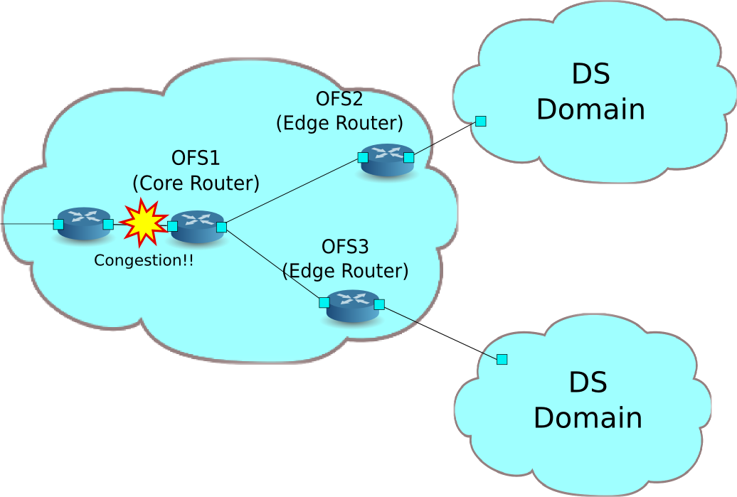
The following shows an example of the network composed of the multiple DiffServ domain (DS domain). Traffic metering are executed by the router (edge router) located on the boundary of the DS domain, and the traffic that exceeds the specified bandwidth will be re-marking. Usually, re-marked packets are dropped preferentially or treated as low priority class. In this example, perform the bandwidth guarantee of 800Kbps to AF1 class. Also, AF11 class traffic transferred from each DS domain is guaranteed with 400Kbps bandwidth. Traffic that is more than 400kbps is treated as excess traffic, and re-marked with AF12 class. However, it is still guaranteed that AF12 class is more preferentially transferred than the best effort class.
Building the environment
First, build an environment on Mininet. Build a topology using a python script.
source code: qos_sample_topology.py
from mininet.net import Mininet
from mininet.cli import CLI
from mininet.topo import Topo
from mininet.node import UserSwitch
from mininet.node import RemoteController

class SliceableSwitch(UserSwitch):
    def __init__(self, name, **kwargs):
        UserSwitch.__init__(self, name, '', **kwargs)

class MyTopo(Topo):
    def __init__( self ):
        "Create custom topo."
        # Initialize topology
        Topo.__init__( self )
        # Add hosts and switches
        host01 = self.addHost('h1')
        host02 = self.addHost('h2')
        host03 = self.addHost('h3')
        switch01 = self.addSwitch('s1')
        switch02 = self.addSwitch('s2')
        switch03 = self.addSwitch('s3')
        # Add links
        self.addLink(host01, switch01)
        self.addLink(host02, switch02)
        self.addLink(host03, switch03)
        self.addLink(switch01, switch02)
        self.addLink(switch01, switch03)

def run(net):
    s1 = net.getNodeByName('s1')
    s1.cmdPrint('dpctl unix:/tmp/s1 queue-mod 1 1 80')
    s1.cmdPrint('dpctl unix:/tmp/s1 queue-mod 1 2 120')
    s1.cmdPrint('dpctl unix:/tmp/s1 queue-mod 1 3 800')

def genericTest(topo):
    net = Mininet(topo=topo, switch=SliceableSwitch,
        controller=RemoteController)
    net.start()
    run(net)
    CLI(net)
    net.stop()

def main():
    topo = MyTopo()
    genericTest(topo)

if __name__ == '__main__':
    main()
Note
Change the link speed of ofsoftswitch13 to 1Mbps in advance.
First, modify the sourcecode of ofsoftswitch13.
$ cd ofsoftswitch13
$ gedit lib/netdev.c
lib/netdev.c:
644           if (ecmd.autoneg) {
645               netdev->curr |= OFPPF_AUTONEG;
646           }
647
648 -         netdev->speed = ecmd.speed;
649 +         netdev->speed = 1;  /* Fix to 1Mbps link */
650
651       } else {
652           VLOG_DBG(LOG_MODULE, "ioctl(SIOCETHTOOL) failed: %s", strerror(errno));
653       }
Then, re-install ofsoftswitch13.
$ make clean
$ ./boot.sh
$ ./configure
$ make
$ sudo make install
An execution example is as follows.
$ curl -O https://raw.githubusercontent.com/osrg/ryu-book/master/sources/qos_sample_topology.py
$ sudo python ./qos_sample_topology.py
Unable to contact the remote controller at 127.0.0.1:6633
mininet>
Also, start two xterm for the controller.
mininet> xterm c0
mininet> xterm c0
mininet>
Next, modify the simple_switch_13.py used in “Switching Hub”. rest_qos.py suppose to be processed on Flow Table pipeline processing,modify simple_switch_13.py to register flow entry into table id:1.
controller: c0 (root)
# sed '/OFPFlowMod(/,/)/s/)/, table_id=1)/' ryu/ryu/app/simple_switch_13.py > ryu/ryu/app/qos_simple_switch_13.py
# cd ryu/; python ./setup.py install
Finally, start rest_qos and qos_simple_switch_13 on xterm of controller.
controller: c0 (root):
# ryu-manager ryu.app.rest_qos ryu.app.qos_simple_switch_13
loading app ryu.app.rest_qos
loading app ryu.app.qos_simple_switch_13
loading app ryu.controller.ofp_handler
loading app ryu.controller.ofp_handler
loading app ryu.controller.ofp_handler
instantiating app None of DPSet
creating context dpset
instantiating app None of ConfSwitchSet
creating context conf_switch
creating context wsgi
instantiating app ryu.app.qos_simple_switch_13 of SimpleSwitch13
instantiating app ryu.controller.ofp_handler of OFPHandler
instantiating app ryu.app.rest_qos of RestQoSAPI
(2348) wsgi starting up on http://0.0.0.0:8080/
After a successful connection between the switch and Ryu, the following message appears.
controller: c0 (root):
[QoS][INFO] dpid=0000000000000003: Join qos switch.
[QoS][INFO] dpid=0000000000000001: Join qos switch.
[QoS][INFO] dpid=0000000000000002: Join qos switch.
...
Setting QoS
Install the following flow entry in accordance with DSCP value into the router (s1).
| (Priority) | DSCP | Queue ID | (QoS ID) |
|---|---|---|---|
| 1 | 0 (BE) | 1 | 1 |
| 1 | 12(AF12) | 2 | 2 |
| 1 | 10(AF11) | 3 | 3 |
Node: c0 (root):
# curl -X POST -d '{"match": {"ip_dscp": "0", "in_port": "2"}, "actions":{"queue": "1"}}' http://localhost:8080/qos/rules/0000000000000001
  [
    {
      "switch_id": "0000000000000001",
      "command_result": [
        {
          "result": "success",
          "details": "QoS added. : qos_id=1"
        }
      ]
    }
  ]

# curl -X POST -d '{"match": {"ip_dscp": "10", "in_port": "2"}, "actions":{"queue": "3"}}' http://localhost:8080/qos/rules/0000000000000001
  [
    {
      "switch_id": "0000000000000001",
      "command_result": [
        {
          "result": "success",
          "details": "QoS added. : qos_id=2"
        }
      ]
    }
  ]

# curl -X POST -d '{"match": {"ip_dscp": "12", "in_port": "2"}, "actions":{"queue": "2"}}' http://localhost:8080/qos/rules/0000000000000001
  [
    {
      "switch_id": "0000000000000001",
      "command_result": [
        {
          "result": "success",
          "details": "QoS added. : qos_id=3"
        }
      ]
    }
  ]

# curl -X POST -d '{"match": {"ip_dscp": "0", "in_port": "3"}, "actions":{"queue": "1"}}' http://localhost:8080/qos/rules/0000000000000001
  [
    {
      "switch_id": "0000000000000001",
      "command_result": [
        {
          "result": "success",
          "details": "QoS added. : qos_id=4"
        }
      ]
    }
  ]

# curl -X POST -d '{"match": {"ip_dscp": "10", "in_port": "3"}, "actions":{"queue": "3"}}' http://localhost:8080/qos/rules/0000000000000001
  [
    {
      "switch_id": "0000000000000001",
      "command_result": [
        {
          "result": "success",
          "details": "QoS added. : qos_id=5"
        }
      ]
    }
  ]

# curl -X POST -d '{"match": {"ip_dscp": "12", "in_port": "3"}, "actions":{"queue": "2"}}' http://localhost:8080/qos/rules/0000000000000001
  [
    {
      "switch_id": "0000000000000001",
      "command_result": [
        {
          "result": "success",
          "details": "QoS added. : qos_id=6"
        }
      ]
    }
  ]
Install the following meter entries to the switches (s2, s3).
| (Priority) | DSCP | Meter ID | (QoS ID) | |
|---|---|---|---|---|
| 1 | 10(AF11) | 1 | 1 | |
| Meter ID | Flags | Bands |
|---|---|---|
| 1 | KBPS | type:DSCP_REMARK, rate:400000, prec_level:1 |
# curl -X POST -d '{"match": {"ip_dscp": "10"}, "actions":{"meter": "1"}}' http://localhost:8080/qos/rules/0000000000000002
  [
    {
      "switch_id": "0000000000000002",
      "command_result": [
        {
          "result": "success",
          "details": "QoS added. : qos_id=1"
        }
      ]
    }
  ]

# curl -X POST -d '{"meter_id": "1", "flags": "KBPS", "bands":[{"type":"DSCP_REMARK", "rate": "400", "prec_level": "1"}]}' http://localhost:8080/qos/meter/0000000000000002
  [
    {
      "switch_id": "0000000000000002",
      "command_result": [
        {
          "result": "success",
          "details": "Meter added. : Meter ID=1"
        }
      ]
    }
  ]

# curl -X POST -d '{"match": {"ip_dscp": "10"}, "actions":{"meter": "1"}}' http://localhost:8080/qos/rules/0000000000000003
[
  {
    "switch_id": "0000000000000003",
    "command_result": [
      {
        "result": "success",
        "details": "QoS added. : qos_id=1"
      }
    ]
  }
]

# curl -X POST -d '{"meter_id": "1", "flags": "KBPS", "bands":[{"type":"DSCP_REMARK", "rate": "400", "prec_level": "1"}]}' http://localhost:8080/qos/meter/0000000000000003
  [
    {
      "switch_id": "0000000000000003",
      "command_result": [
        {
          "result": "success",
          "details": "Meter added. : Meter ID=1"
        }
      ]
    }
  ]
Verifying the Setting
Check the contents of the setting of each switch.
Node: c0 (root):
# curl -X GET http://localhost:8080/qos/rules/0000000000000001
  [
    {
      "switch_id": "0000000000000001",
      "command_result": [
        {
          "qos": [
            {
              "priority": 1,
              "dl_type": "IPv4",
              "actions": [
                {
                  "queue": "1"
                }
              ],
              "in_port": 2,
              "qos_id": 1
            },
            {
              "priority": 1,
              "dl_type": "IPv4",
              "actions": [
                {
                  "queue": "3"
                }
              ],
              "qos_id": 2,
              "in_port": 2,
              "ip_dscp": 10
            },
            {
              "priority": 1,
              "dl_type": "IPv4",
              "actions": [
                {
                  "queue": "2"
                }
              ],
              "qos_id": 3,
              "in_port": 2,
              "ip_dscp": 12
            },
            {
              "priority": 1,
              "dl_type": "IPv4",
              "actions": [
                {
                  "queue": "1"
                }
              ],
              "in_port": 3,
              "qos_id": 4
            },
            {
              "priority": 1,
              "dl_type": "IPv4",
              "actions": [
                {
                  "queue": "3"
                }
              ],
              "qos_id": 5,
              "in_port": 3,
              "ip_dscp": 10
            },
            {
              "priority": 1,
              "dl_type": "IPv4",
              "actions": [
                {
                  "queue": "2"
                }
              ],
              "qos_id": 6,
              "in_port": 3,
              "ip_dscp": 12
            }
          ]
        }
      ]
    }
  ]

# curl -X GET http://localhost:8080/qos/rules/0000000000000002
  [
    {
      "switch_id": "0000000000000002",
      "command_result": [
        {
          "qos": [
            {
              "priority": 1,
              "dl_type": "IPv4",
              "ip_dscp": 10,
              "actions": [
                {
                  "meter": "1"
                }
              ],
              "qos_id": 1
            }
          ]
        }
      ]
    }
  ]

# curl -X GET http://localhost:8080/qos/rules/0000000000000003
  [
    {
      "switch_id": "0000000000000003",
      "command_result": [
        {
          "qos": [
            {
              "priority": 1,
              "dl_type": "IPv4",
              "ip_dscp": 10,
              "actions": [
                {
                  "meter": "1"
                }
              ],
              "qos_id": 1
            }
          ]
        }
      ]
    }
  ]
Measuring the bandwidth
Try to measure the bandwidth by using iperf. h1(server) is listening on port 5001 and 5002 and port 5003 in the UDP protocol. h2, h3 (client) sends the traffic of each class addressed to h1.
First, start 4 xterm as follows.
mininet> xterm h1
mininet> xterm h2
mininet> xterm h3
mininet> xterm h3
...
Node: h1(1) (root):
# iperf -s -u -p 5001 &
# iperf -s -u -p 5002 &
# iperf -s -u -p 5003 &
...
Best-effort traffic & AF11 excess traffic
Node: h2 (root):
# iperf -c 10.0.0.1 -p 5001 -u -b 800K
------------------------------------------------------------
Client connecting to 10.0.0.1, UDP port 5001
Sending 1470 byte datagrams
UDP buffer size:  208 KByte (default)
------------------------------------------------------------
[  4] local 10.0.0.3 port 60324 connected with 10.0.0.1 port 5001
[ ID] Interval       Transfer     Bandwidth
[  4]  0.0-10.0 sec   979 KBytes   800 Kbits/sec
[  4] Sent 682 datagrams
[  4] Server Report:
[  4]  0.0-11.9 sec   650 KBytes   449 Kbits/sec  18.458 ms  229/  682 (34%)
Node: h3(1) (root):
# iperf -c 10.0.0.1 -p 5002 -u -b 600K --tos 0x28
------------------------------------------------------------
Client connecting to 10.0.0.1, UDP port 5002
Sending 1470 byte datagrams
UDP buffer size:  208 KByte (default)
------------------------------------------------------------
[  4] local 10.0.0.2 port 53661 connected with 10.0.0.1 port 5002
[ ID] Interval       Transfer     Bandwidth
[  4]  0.0-10.0 sec   735 KBytes   600 Kbits/sec
[  4] Sent 512 datagrams
[  4] Server Report:
[  4]  0.0-10.0 sec   735 KBytes   600 Kbits/sec   7.497 ms    6/  512 (1.2%)
[  4]  0.0-10.0 sec  6 datagrams received out-of-order
The above result shows, even if the traffic of AF11 exceeds the contracted bandwidth 400Kbps, AF11 is more preferentially guaranteed bandwidth than traffic of best effort.
AF11 excess traffic & Best-effort traffic & AF11 non-excess traffic
Node: h2 (root):
# iperf -c 10.0.0.1 -p 5001 -u -b 600K --tos 0x28
------------------------------------------------------------
Client connecting to 10.0.0.1, UDP port 5001
Sending 1470 byte datagrams
UDP buffer size:  208 KByte (default)
------------------------------------------------------------
[  4] local 10.0.0.2 port 49358 connected with 10.0.0.1 port 5001
[ ID] Interval       Transfer     Bandwidth
[  4]  0.0-10.0 sec   735 KBytes   600 Kbits/sec
[  4] Sent 512 datagrams
[  4] Server Report:
[  4]  0.0-10.0 sec   666 KBytes   544 Kbits/sec  500.361 ms   48/  512 (9.4%)
[  4]  0.0-10.0 sec  192 datagrams received out-of-order
Node: h3(1) (root):
# iperf -c 10.0.0.1 -p 5002 -u -b 500K
------------------------------------------------------------
Client connecting to 10.0.0.1, UDP port 5002
Sending 1470 byte datagrams
UDP buffer size:  208 KByte (default)
------------------------------------------------------------
[  4] local 10.0.0.3 port 42759 connected with 10.0.0.1 port 5002
[ ID] Interval       Transfer     Bandwidth
[  4]  0.0-10.0 sec   613 KBytes   500 Kbits/sec
[  4] Sent 427 datagrams
[  4] WARNING: did not receive ack of last datagram after 10 tries.
[  4] Server Report:
[  4]  0.0-14.0 sec   359 KBytes   210 Kbits/sec  102.479 ms  177/  427 (41%)
Node: h3(2) (root):
# iperf -c 10.0.0.1 -p 5003 -u -b 400K --tos 0x28
------------------------------------------------------------
Client connecting to 10.0.0.1, UDP port 5003
Sending 1470 byte datagrams
UDP buffer size:  208 KByte (default)
------------------------------------------------------------
[  4] local 10.0.0.3 port 35475 connected with 10.0.0.1 port 5003
[ ID] Interval       Transfer     Bandwidth
[  4]  0.0-10.1 sec   491 KBytes   400 Kbits/sec
[  4] Sent 342 datagrams
[  4] Server Report:
[  4]  0.0-10.5 sec   491 KBytes   384 Kbits/sec  15.422 ms    0/  342 (0%)
The above result shows, traffic within the contracted bandwidth of 400Kbps are not dropped.
AF11 excess traffic & AF11 excess traffic
Node: h2 (root):
# iperf -c 10.0.0.1 -p 5001 -u -b 600K --tos 0x28
------------------------------------------------------------
Client connecting to 10.0.0.1, UDP port 5001
Sending 1470 byte datagrams
UDP buffer size:  208 KByte (default)
------------------------------------------------------------
[  4] local 10.0.0.3 port 50761 connected with 10.0.0.1 port 5001
[ ID] Interval       Transfer     Bandwidth
[  4]  0.0-10.0 sec   735 KBytes   600 Kbits/sec
[  4] Sent 512 datagrams
[  4] Server Report:
[  4]  0.0-11.0 sec   673 KBytes   501 Kbits/sec  964.490 ms   43/  512 (8.4%)
[  4]  0.0-11.0 sec  95 datagrams received out-of-order
Node: h3(1) (root):
# iperf -c 10.0.0.1 -p 5002 -u -b 600K --tos 0x28
------------------------------------------------------------
Client connecting to 10.0.0.1, UDP port 5002
Sending 1470 byte datagrams
UDP buffer size:  208 KByte (default)
------------------------------------------------------------
[  4] local 10.0.0.2 port 53066 connected with 10.0.0.1 port 5002
[ ID] Interval       Transfer     Bandwidth
[  4]  0.0-10.0 sec   735 KBytes   600 Kbits/sec
[  4] Sent 512 datagrams
[  4] Server Report:
[  4]  0.0-10.6 sec   665 KBytes   515 Kbits/sec  897.126 ms   49/  512 (9.6%)
[  4]  0.0-10.6 sec  93 datagrams received out-of-order
The above result shows, two excess traffic are droped in the same rate.
In this section, you learned how to use the QoS REST API with specific examples.
REST API List
A list of REST API of rest_qos introduced in this section.
Get queue status
| Method | GET |
| URL | /qos/queue/status/{switch} –switch: [ “all” | Switch ID ] |
Get queue configuration
| Method | GET |
| URL | /qos/queue/{switch} –switch: [ “all” | Switch ID ] |
| Remarks | It is possible to get only queue configuration after start of the QoS REST API. |
Set queue
| Method | POST |
| URL | /qos/queue/{switch} –switch: [ “all” | Switch ID ] |
| Data | port_name:[Port name] type:[linux-htb | linux-hfsc] max_rate:[Bandwidth(bps)] queues:
|
| Remarks | If an action of the given type exists in the current set, overwrite it. This command is compatible with only Open vSwitch. port_name on Data is optional. If you do not specify a port_name, it is set to OFPP_ANY. |
Delete queue
| Method | DELETE |
| URL | /qos/queue/{swtich} –switch: [ “all” | Switch ID ] |
| Remarks | Remove the association with QoS record of OVSDB |
Get all of QoS rules
| Method | GET |
| URL | /qos/rules/{switch}[/{vlan}] –switch: [ “all” | Switch ID ] –vlan: [ “all” | VLAN ID ] |
| Remarks | VLAN ID on URL is optional. |
Set a QoS rule
| Method | POST |
| URL | /qos/rules/{switch}[/{vlan}] –switch: [ “all” | Switch ID ] –vlan: [ “all” | VLAN ID ] |
| Data | priority:[ 0 - 65535 ] match:
|
| Remarks | If successful registration, QoS ID is generated, it will be described in the response. VLAN ID on URL is optional. |
Delete qos rules
| Method | DELETE |
| URL | /qos/rules/{switch}[/{vlan}] –switch: [ “all” | Switch ID ] –vlan: [ “all” | VLAN ID ] |
| Data | rule_id:[ “all” | 1 - ... ] |
| Remarks | VLAN ID on URL is optional. |
Get Meter Statistics
| Method | GET |
| URL | /qos/meter/{switch} –switch: [ “all” | Switch ID ] |
Set meter table
| Method | POST |
| URL | /qos/meter/{switch} |
| Data | meter_id:Meter ID bands:
|
| Remarks | The parameter specified or enabled in the bands is depends on the action and flags. |